

HD30852 RF Amplifier
Module
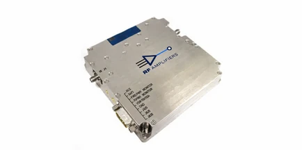
HD30852
| FREQUENCY RANGE24,000–31,000 MHz | OUTPUT POWER6 W (catalog) |
| GAIN38 dB minimum | SUPPLY VOLTAGE20 VDC Nom |
| CONFIGURATIONModule | CATEGORYMillimeter Amplifier Module |
HD30852 electrical specifications
Source: HD30852 V1.4.pdf. Refer to the complete datasheet for all test conditions, optional ratings and protection limits.
| Parameter | Specification | Conditions / notes |
|---|---|---|
| Operating Frequency Range | 24.0 – 25.0 GHz | 25.0 – 31.0 GHz | |
| Power Output | 4 W typical | 6 W minimum | |
| Power Gain | 38 dB minimum | |
| Power Gain Flatness | 6 dB p-p maximum | 4.0 dB p-p maximum | Constant input power |
| Input Return Loss | 9 dB minimum / >10 dB typical | Relative to 50 Ohm |
| Harmonics | <-20 dBc typical | At rated Pout |
| Operating Voltage | 20 VDC Nom | |
| Current Consumption | 5 A maximum / 4 A typical | At rated Pout |
HD30852 control and monitoring
| Pin | Function | Description |
|---|---|---|
| 1 | N/c | Reserved |
| 2 | N/c | Reserved |
| 5 | SHUTDOWN | TTL |
| 6,7 | VDD | 20 VDC |
| 8,9 | GND | Ground |
Confirm connector orientation and optional functions against the complete model-specific documentation before wiring.
Operating and storage conditions
| Parameter | Specification | Conditions / notes |
|---|---|---|
| Operating Case Temperature | -20 to +65 °C | |
| Storage Temperature | -40 to +85 °C |
Mechanical specifications and cooling
| Parameter | Specification | Conditions / notes |
|---|---|---|
| RF Connectors In/Out | SMA K Type female | |
| DC Power / Interface Connector | 9-Pin D-Sub |
Use the original outline drawing for mounting-hole positions, connector clearances and ordered options.
HD30852 documentation
Download HD30852 V1.4.pdf for the complete specifications, test conditions, drawings and available options.
About HD30852
HD30852 is listed for 24,000–31,000 MHz operation.
Output: 6 W (catalog). Gain: 38 dB minimum. Preserve the rating definitions and conditions in the complete datasheet.
Supply: 20 VDC Nom. Confirm cooling and installation requirements in the datasheet.
See the model-specific interface table above. Optional functions must be confirmed for the ordered unit.
Review the mechanical table and original outline drawing before planning mounting and connector clearances.
Protection ratings are subject to the datasheet conditions and time limits. They do not imply unlimited operation under overload or mismatch.