

RF amplifier applications
Start with your signal, test environment and integration needs. Explore application considerations for RF amplifier systems and modules.
Match the amplifier to the job
EMC / EMI / RFI testing
For RF test setups, define the frequency sweep, modulation and power needed at the load. Include cable and fixture losses, mismatch conditions and monitoring requirements.
Selection priorities: bandwidth, gain flatness, harmonics and the exact protection limits. HD31217 lists EMC/EMI/RFI and laboratory applications in its datasheet; suitability for a specific test method still requires review.
Laboratory & component testing
Build a repeatable stimulus chain for measurements, development and characterization. Specify available source power, required output level and the operating range of downstream equipment.
Selection priorities: gain, P1 dB, noise and spurious output, connector types and cooling.
Communications development
For single-channel and modulated-signal development, define the occupied bandwidth, modulation and acceptable distortion. Saturated output alone does not establish usable linear power.
Selection priorities: P1 dB, two-tone IMD test conditions, gain flatness and required output back-off.
Pulsed RF test setups
Provide pulse width, repetition rate, duty cycle and required peak and average power. Confirm that the selected model explicitly supports the requested waveform and timing.
Selection priorities: rated pulse conditions, switching behavior, power supply and thermal load. A CW rating is not a substitute for a pulse specification.
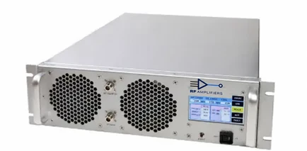
OEM equipment integration
A module can fit into a larger instrument or subsystem when the host design supplies the required power, cooling, controls and mechanical support.
Selection priorities: supply current, heatsink interface, connector clearances, shutdown logic and model-specific pin assignments.
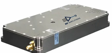
Microwave & narrowband evaluation
Define the exact operating band, not only the nominal center frequency. Check connector suitability, available gain and output level across the required bandwidth.
Selection priorities: band edges, gain flatness, compression and fixture losses. The HD35253 datasheet provides one narrowband 25 GHz example.
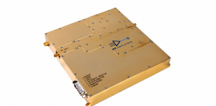
Choose the right integration format
RF amplifier systems
Consider a system for a bench, rack or test installation where an integrated configuration is useful. Review the actual model’s power input, cooling, local controls and remote interfaces.
Do not assume every system includes the same monitoring or interface options.
RF amplifier modules
Consider a module when it will become part of your own equipment. Plan DC supply capacity, external cooling where specified, grounding, shielding and control wiring.
Use the exact model drawing and pin table before laying out the assembly.
Bring the operating conditions into the conversation
- Define the signal: frequency range, waveform, modulation and pulse timing.
- Define output: power at the load, CW or pulse rating, and linearity target.
- Define integration: System or Module, available supply, cooling and space.
- Review the source: confirm datasheet revision, minimum/typical/maximum values and optional functions.
- Request a review: include quantity, schedule and the conditions that matter to your application.
Answers for your next design decision
Those values help narrow the catalog, but waveform, linearity, duty cycle, supply and cooling must also match the application.
No. Application guidance is a starting point for selection. Confirm any required test standard, certification and equipment-level compliance separately.
Include frequency range, desired output and its rating definition, source level, modulation or pulse timing, System/Module preference, supply, cooling, quantity and delivery needs.


