

RF AMPLIFIERS · TECHNICAL GUIDE
Planning an RF Amplifier Power Budget for EMC Testing
An EMC test requirement is not the same as an amplifier’s front-panel wattage rating. The amplifier operates inside a chain that can include cables, switches, couplers, antennas or injection devices. Planning the power budget means identifying what is required at the relevant reference plane and what the signal loses before it gets there.
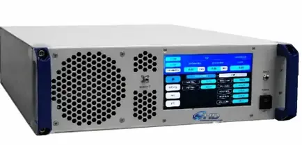
This worksheet supports amplifier selection. It does not replace the applicable test standard, calibrated test method or a laboratory’s uncertainty assessment.
01 / ENGINEERING REVIEW
Start with the test requirement
Record the frequency range, test method, required field or injected level, modulation and any dwell or duty-cycle conditions. Identify the standard and revision used by the laboratory. Different arrangements can require different amplifier capabilities even when the headline frequency range looks similar.
For radiated testing, a field-strength requirement cannot be converted into amplifier power using cable loss alone. Antenna characteristics, geometry, calibration and the test environment matter. Use the laboratory’s validated method to establish the power requirement at the appropriate point.
02 / ENGINEERING REVIEW
Draw the RF chain and label reference planes
Sketch the signal generator, amplifier, monitoring components, cables and final load or transducer. Mark where power is specified, where it is measured and where the test level is established.
List the loss of each intervening component across frequency. Use suitable measured data or guaranteed specifications rather than a single convenient value. Keep monitoring sample losses separate from main-path losses so the same loss is not counted twice.
03 / ENGINEERING REVIEW
A simplified power-budget example
Assume, solely for illustration, that a validated setup requires 40 dBm at a defined connector reference plane. If the components between the amplifier output and that point contribute 3 dB of loss at the frequency being considered, the starting estimate is 43 dBm at the amplifier output.
In linear units, 40 dBm is 10 watts and 43 dBm is approximately 20 watts. This arithmetic describes a simple matched RF path. It does not establish a radiated field level, account for every uncertainty or prove that a nominal 20-watt amplifier will meet the test.
The next step is to assess the waveform, linearity requirement, frequency-dependent output and operating conditions. Any headroom should have an explained purpose rather than being added as an arbitrary percentage.
04 / ENGINEERING REVIEW
Distinguish usable linear output from saturation
Compare the output specification relevant to the test. Saturated output power and output at 1 dB compression describe different operating points. A modulated signal may require additional evaluation of distortion and peak behavior.
Our P1dB versus Psat guide explains the distinction. Do not assume a saturation rating is available as undistorted output across the full band.
05 / ENGINEERING REVIEW
Check the load and mismatch conditions
The load seen by the amplifier may vary with frequency and test configuration. Ask what mismatch the amplifier can tolerate, what protection does when triggered and whether power is reduced under particular conditions. A protection feature and sustained output performance are different specifications.
AR’s EMC amplifier selection guidance provides additional context on application requirements. Evaluate any candidate against the conditions of your own setup.
06 / ENGINEERING REVIEW
Power-budget worksheet
- Test standard, revision, method and frequency range.
- Required level and its defined reference plane.
- Waveform, modulation, peak behavior and operating duration.
- Main-path losses versus frequency, with data sources.
- Required amplifier output at each important frequency.
- Applicable linearity or compression limit.
- Expected load mismatch and required operating response.
- Cooling, supply, control and monitoring requirements.
- Acceptance method and measurement documentation.
Review the limiting frequencies rather than relying on a band-average result. Preserve the assumptions with the calculation so another engineer can understand how the requirement was derived.
07 / NEXT STEPS
Turn the budget into an amplifier request
Use our RF amplifier selection guide and browse broadband amplifiers. Then send RF Amplifiers your power-budget worksheet, test conditions and timing so the requirement can be reviewed against specific products.