

RF AMPLIFIERS · TECHNICAL GUIDE
RF Amplifier Cooling and Thermal Integration
Verify the heat-removal path and temperature reference before relying on an electrical rating.
01 / ENGINEERING REVIEW
Identify the temperature being specified
Ambient, case, baseplate and junction temperatures are different quantities. A limit stated for one cannot be applied directly to another. Read the datasheet’s reference point and installation conditions.
02 / ENGINEERING REVIEW
Account for the thermal path
Heat travels through the device, mounting interface, heatsink and surrounding environment. Thermal resistance relates dissipated power to temperature rise under defined conditions. An RF output-power value alone is insufficient to size the cooling system.
03 / ENGINEERING REVIEW
Integration checklist
- Obtain supply-consumption and heat-dissipation information.
- Confirm mounting surface, interface material and fastening requirements.
- Check airflow direction, clearance and permitted ambient conditions.
- Review pulse duty cycle and thermal derating where applicable.
- Confirm monitoring, interlocks and overtemperature behavior.
Do not assume a module includes a heatsink, or that a system can operate in a sealed rack. Confirm what the quoted configuration includes.
04 / ENGINEERING REVIEW
Model-specific review
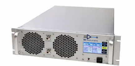
HD31621 provides a pulse-system example with its own environmental limits. Use the linked document and request installation instructions before finalizing the enclosure. In the RFQ, describe rack space, airflow, ambient range, duty cycle and available supply.
05 / NEXT STEPS
Continue your technical review
View HD31621 · HD31621 datasheet (PDF) · Search all products · Request a quote
General selection guidance. The current model-specific datasheet and agreed configuration govern product limits.