

RF AMPLIFIERS · TECHNICAL GUIDE
VSWR and Load Mismatch for RF Amplifiers
A port-match specification and a survivable load-mismatch limit answer different engineering questions.
01 / ENGINEERING REVIEW
What VSWR describes
VSWR expresses impedance mismatch. A 1:1 value represents an ideal match; higher values indicate greater reflection. Real cables, connectors and loads can change the response seen by the amplifier across frequency.
02 / ENGINEERING REVIEW
Do not confuse match with protection
An input or output VSWR specification does not, by itself, state how much reflected power the amplifier can tolerate. Request the permitted load VSWR, power, duration and other conditions, plus details of any protection or recovery behavior.
03 / ENGINEERING REVIEW
Before connecting the load
- Confirm nominal impedance throughout the RF path.
- Check cable, connector, load and measuring-device frequency and power ratings.
- Review mismatch limits in the exact amplifier document.
- Confirm whether the installation requires isolation or monitoring.
- Use the manufacturer’s operating procedure and approved test setup.
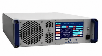
Do not perform open-circuit, short-circuit or full-power mismatch tests without an explicit approved procedure. Review HD31692 and its datasheet as a catalog starting point; its listing does not establish protection features that the document does not state.
04 / ENGINEERING REVIEW
RFQ details
Include the expected load match over frequency and any abnormal-load conditions the system must handle.
05 / NEXT STEPS
Continue your technical review
View HD31692 · HD31692 datasheet (PDF) · Search all products · Request a quote
General selection guidance. The current model-specific datasheet and agreed configuration govern product limits.